Fourth-year undergraduate student pursuing two B.S in Mechanical Engineering and Aerospace Engineering.
Wind tunnel Simulation Analysis, and Structural Analysis
Undergraduate Aerospace Engineering course individual project (04/2022)
Air tunnel simulation with hemisphere inside using CATIA and StarCCM+. Structural Analysis under loads and design improvements.
Wind tunnel simulation with hemisphere inside
Set-up
Modelled Tunnel and hemisphere in CATIA with Boolean operations.
Simulations with STARCAT5.
Boundary Conditions imposed on body:
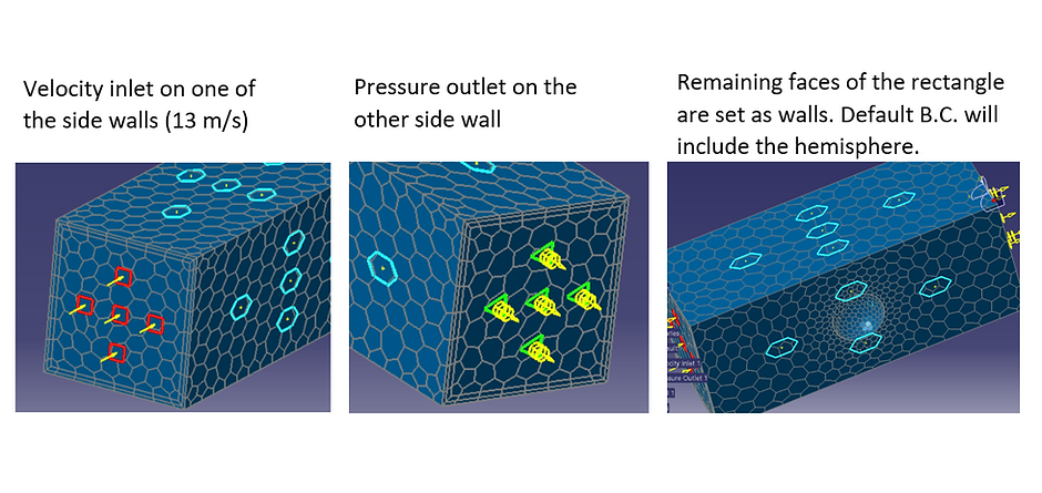
Velocity inlet on one side of the walls.
Pressure outlet on the other side wall.
Remaining faces of the tunnel are set as walls.
The default B.C. will include the hemisphere.
 |  |
|---|
Analysis
Flow Analysis:
At the top: Maximum velocity achieved (red and orange arrows). Flow is primarily tangential (arrows pointing in the flow's direction).
Lower Right and Left side: Stagnation points where higher pressure is obtained on the surface. At these points, velocity attains low values (near 0 m/s)
Bernoulli streamlines analysis: at minimum velocity values, pressure is at maximum, especially on the lower right-hand side of the craft. The flow goes around the craft almost tangentially, which makes sense since flow cannot penetrate the body.
Aerodynamic Forces:
Higher pressure on the lower right side of the hemisphere, i.e., Stagnation point
Flow towards the left, higher forces are mainly applied on the right side. I.e., the force points towards the left.
A maximum of 90.705 Pa acts on a small surface area of the hemisphere.
Force analysis on the hemisphere: -0.3813 N in the x-direction, -0.01819N in the y-direction, and 3.2816N in the z-direction
The strongest force magnitude is along the z-direction (perpendicular to the flow), which gives lift to the hovercraft.
Structural Analysis of a Plexiglass Motor Mount
Original model:
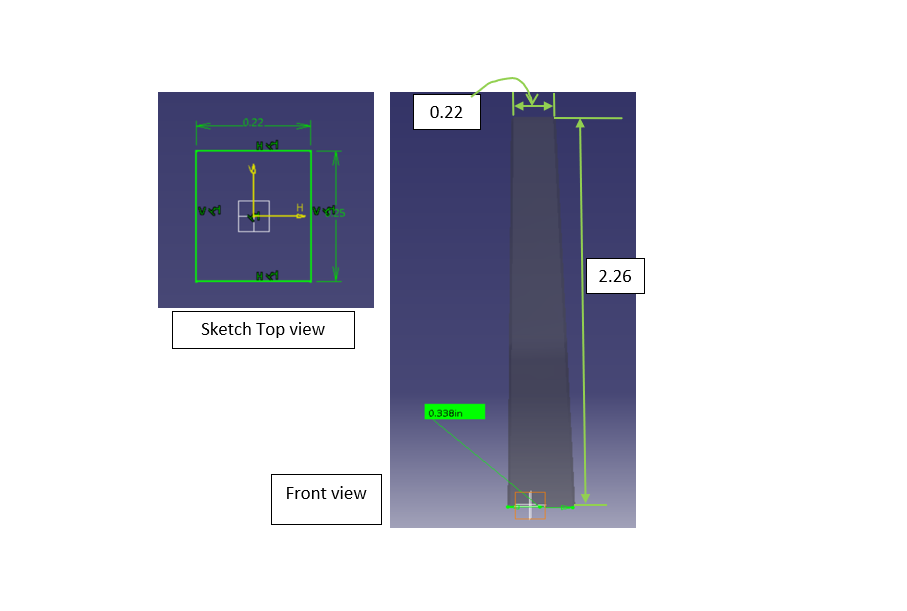
A supporting motor mount made of plexiglass, with dimensions: 1/4" x 1/4" x 2.7". Motor hot-glued to the mount and mount glued to the top of the hovercraft shell. Motor rotates the propeller and does not revolve around the mount.
Assumptions:
Motor's diameter: 1/2"
Produces up to 1.5N of thrust
Propeller's diameter: 5"
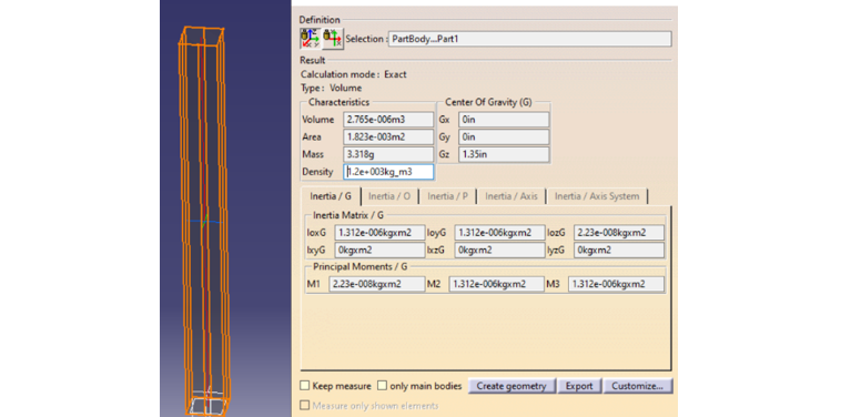
CATIA Model:
Mass: 3.318 grams
Geometric properties shown on the picture below.
Analysis on original model
Loads acting on system:
Axial thrust of motor acting on motor mount.
Modelled applying distributed forces on top surface where motor mount is attached to the motor.
Load acts on x-direction, 1.5N.
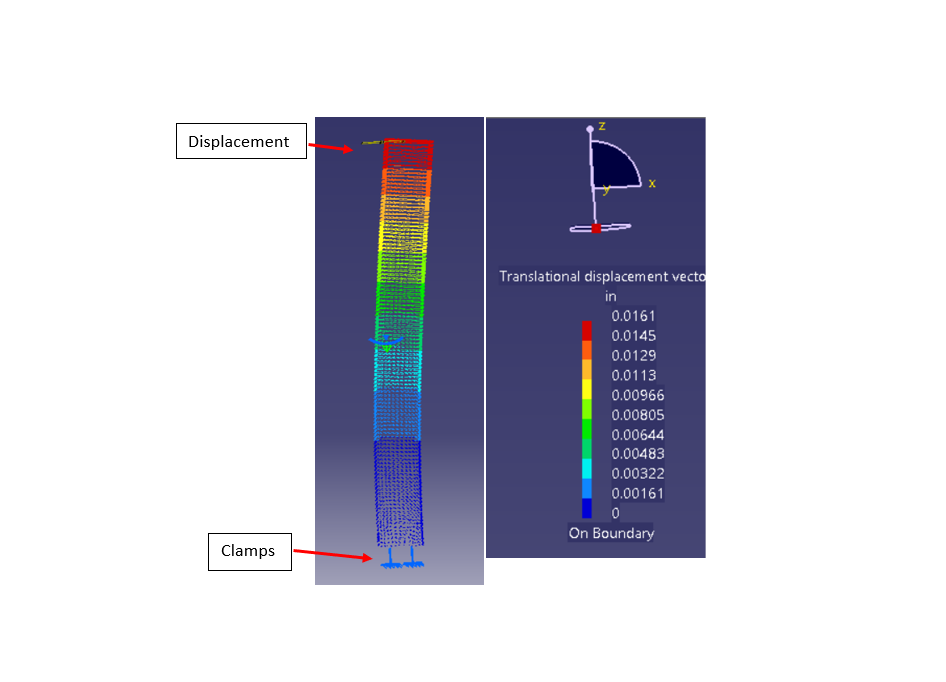
Bottom surface is clamped to simulate it being glued to the hovercraft.
Sanity check: zero deformation at the clamps - correct since it was an imposed condition, the simulation must retain it.
Maximum displacement:
Max. displacement occurs at vicinity of the load
There are higher displacement at the top as indicated by the red arrows pointing in the x-direction.
Sanity check: Direction is correct since axial thrust applies shear stress on surface, towards the right.
Maximum translational displacement is 0.0161" to the right.
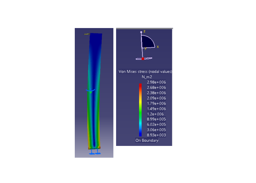
Maximum Stress:
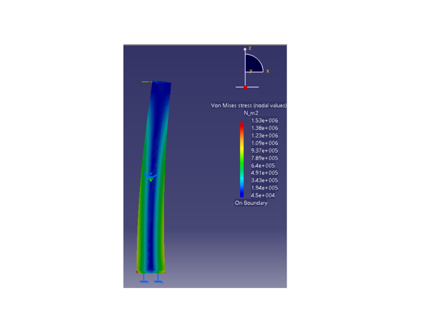
Von mises stress model on the mount.
Maximum stress is 2.98 MPa, it occurs at the bottom where the mount is attached to the shell.
Note:
For an actual motor mount, the moment due to the propeller (blades) should be considered. Its weight generates a moment on the mount that could cause it to bend more.
Also, consider the motor's mass. If quantity was given, it could be possible to analyze if it adds a considerable axial force on the mount that would compress it.
Improved Model:
Requirements:
Reduce maximum deflection by half
Maintain or reduce the maximum stress
Reduce the mass
Execution:
New mount design:
Rectangular base of 0.22" by 0.25", and a height: 2.26".
A draft angle of 3° with respect to the top surface.
Results:
Reduced mass from 3.318 grams to 3.102 grams.
Reduced displacement by more than 1/2. From 0.0161" to 0.00527".
Reduced the stress from approximately 2.98 MPa to 1.53 MPa.